
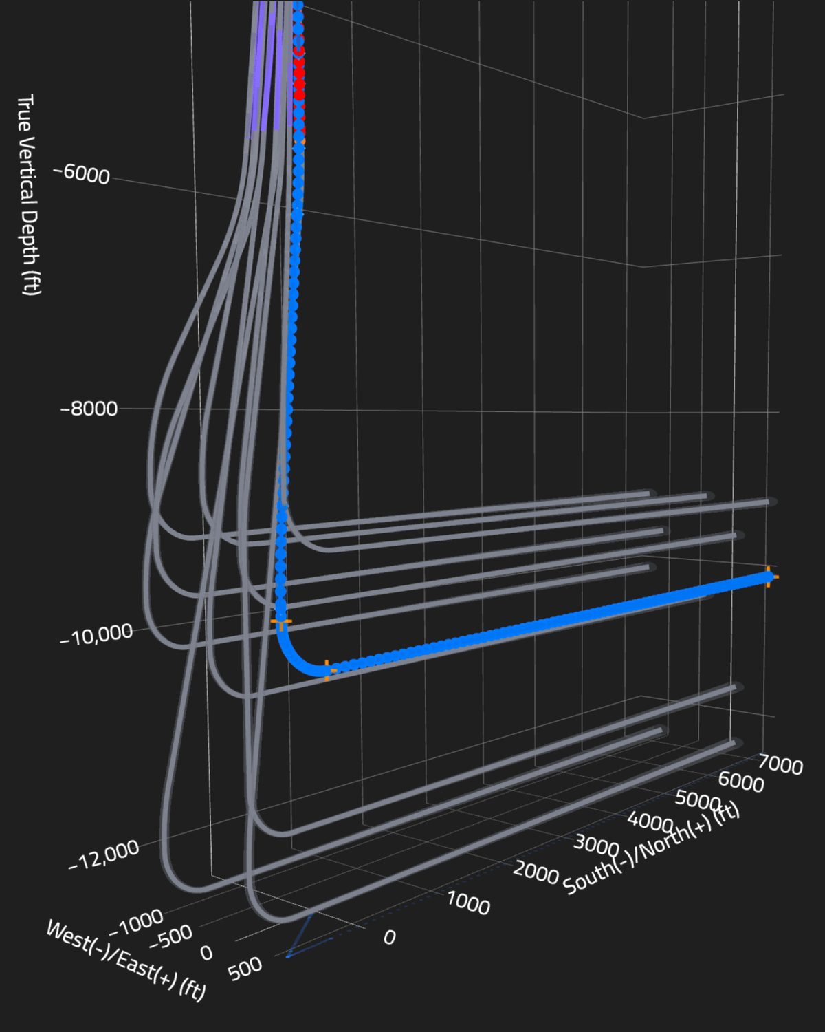
Anti-collision well planning prevents wellbore collisions by calculating center-to-center distance between the planned well and every offset, wrapping each path in its survey uncertainty, and checking the resulting separation factor against a set rule before spud. On a high-density pad, that work is done in the plan, and the rig confirms it with every survey.
A sidetrack on a Permian pad usually costs more than lost footage. The rig sits on location while the next well in the batch waits, the frac schedule moves, and the offset you came close to may need its own diagnostics. Most of those days can be traced back to the plan, not the bit. This post covers what we check on pads with tight surface spacing and stacked targets, and where the plans we see tend to go wrong.
Specialized Energy Services provides directional drilling, well planning, and live geosteering for operators in the Permian Basin, Delaware Basin, and South Texas. Across 134 wells and 1,974,067 feet drilled, our anti-collision work has been part of the planning package from the first draft of the plan, not a scan run the week before the rig shows up.
What does anti-collision well planning actually calculate?
The starting point is geometry. Researchers at the British University in Egypt state it directly: the distance between the center of the offset and subject well must be calculated to avoid collision. Distance alone is not enough, because neither wellbore sits exactly where its surveys say it is.
Each survey station has an error ellipse, also called the ellipse of uncertainty (EOU). The ellipse grows with measured depth, tool type, and survey corrections. A useful plan compares three numbers at every depth:
- Center-to-center distance: the straight-line gap between the two well paths.
- Combined uncertainty: the size of both ellipses along the line between them.
- Separation factor: center-to-center distance divided by combined uncertainty. The operator's anti-collision rule sets the minimum allowed value and what happens when a well drops below it.
The math should be checked against a recognized benchmark. ISCWSA, the industry survey accuracy committee, publishes test datasets, and Oliasoft has written up its validation against an ISCWSA case with a reference well and eleven offset wellbores, covering EOU, center-to-center distance, and separation factor. If your planning software has not been validated against those cases, ask for the validation before you trust the numbers on a 10-well pad.
Why are Permian pads harder to plan than single wells?
On a single well, the closest offset is often a legacy vertical a quarter mile away. On a modern Delaware or Midland pad, the closest offsets are on the same pad. Surface holes are close together, and the wells fan out through the same shallow interval before the kickoff. Then some wells cross under or beside producing laterals from an earlier development in a different bench.
Three conditions drive most of the risk we plan around:
- Shallow nudges in a crowded surface section. Most separation problems happen in the top hole, where wells are closest and the smallest ellipses still overlap quickly.
- Stacked benches. When you are drilling Wolfcamp A under an existing Bone Spring lateral, the vertical gap between targets becomes the critical number, and TVD uncertainty matters more than lateral position.
- Old offset surveys. Many legacy wells were surveyed with gyro or single-shot tools that have large error models, or have incomplete records. A poorly surveyed offset carries a big ellipse whether you like it or not.
Pad density also raises the stakes beyond lost hole. Drilling Contractor noted that the close proximity of wells in pad drilling increases the risk of more severe consequences during well control events. Keeping wellbores apart is one layer of that risk control.
How should you set directional well offset spacing at the surface?
Surface layout comes before the directional plan, so fix the problems there first. Things we look at before we draw a single well path:
- Match surface order to bottom-hole order. If well 1 on the north side of the pad lands on the south side of the unit, it crosses its neighbors. Rearrange the slots so the wells fan out without crossing wherever the lease and rig walk allow.
- Stagger kickoff depths. Wells that nudge in different directions at different depths gain separation faster than wells that all kick at the same depth.
- Nudge early, in the right direction. A small, planned nudge right under surface casing is easier to drill and easier to survey than a hard correction later.
- Plan the drilling order. Drill the wells with the toughest geometry first, while they have the fewest new offsets around them, when the rig schedule permits.
How does 3D collision modeling change the plan?
A spider plot (plan view) can hide a problem that the vertical section shows, and the reverse. A 3D model with every ellipse displayed shows where the paths and their uncertainty actually come close. Review it with the operator's drilling engineer and the directional team together, and walk the whole path from surface to TD.
What a good review produces:
- A ranked list of close approaches. Drakewell describes sorting critical points across all offset wells at once, sorted with the worst first. That is the right format. The rig should know the three depths that matter most, not scroll through a 40-page report.
- A survey program tied to those depths. If separation is tight from 1,200 to 2,400 feet, plan tighter survey intervals and the right correction method through that interval.
- Written actions for each threshold. What happens if the separation factor falls below the warning level, and who decides at the stop level. Ohio's rule, posted by ISCWSA, requires a collision avoidance management plan to be developed and implemented for both planning and drilling. Even where that is not required, a written plan stops the company man from having to make the call alone at 2 a.m.
Where do anti-collision plans fail during drilling?
Innova Drilling puts it plainly: anti-collision is not simply about calculating the distance between two wellbores. Survey quality and well type matter as much as the math. The failures we see most often in the field:
- The plan used a better error model than the rig actually runs. If the scan assumed corrected MWD surveys and the rig sends raw ones, the real ellipses are bigger than the plan says.
- Dogleg overshoot in the curve. A motor that builds hotter than planned pulls the well off its line. Projection to bit matters more when separation is tight. We cover the trade-offs between tools in our rotary steerable system vs mud motor comparison.
- Offset data that was never updated. A well drilled on the next pad last month needs its definitive survey loaded before you scan.
- Anti-collision checks that stop after the curve. Lateral spacing between stacked wells still needs monitoring, especially where geosteering moves the wellbore up or down in the target.
How do execution tools support wellbore collision prevention?
A plan is only as good as the well's ability to follow it. Steady, low-tortuosity hole keeps the actual path close to the planned path and reduces the guesswork between survey stations. Rotary steerable systems such as the PowerDrive Orbit G2 and iCruise make smaller, more frequent corrections than slide-and-rotate drilling, which helps in tight top-hole sections. For more on keeping the path smooth, see our guide to reducing wellbore tortuosity in extended reach laterals.
Survey data quality also matters. Our GT-MWD systems provide the survey stream the anti-collision scan depends on, and AI Driller lets the team watch downhole behavior in real time instead of waiting for the next survey to find a trend. We describe that workflow in our post on real-time downhole data and NPT. Tool reliability matters here too. A failed MWD tool in a tight section means a trip or a run of drilling with no surveys. Our fleet has run at 98.97% tool reliability.
Does careful anti-collision planning slow wells down?
Not when it is done early. The planning work happens before spud. On location, it shows up as a short list of depths to watch and a survey program the rig already knows. Wells that follow the plan avoid the stops, extra survey runs, and corrections that cost days. Our fastest spud-to-TD times, 2.11 days in Dimmit County and 4.13 days in Lea County, New Mexico, came from wells where the plan and the execution matched. Clean planning also makes it easier to drill the curve and lateral in one run because there are fewer surprises to stop for.
A pre-spud anti-collision checklist
- All offset surveys loaded, including wells finished in the last 60 days, with the correct error model for each.
- Planning software validated against ISCWSA test cases.
- Surface slot order checked against bottom-hole order.
- Close approaches ranked, with depth, separation factor, and offset name.
- Survey interval and correction method set for each close-approach interval.
- Warning and stop thresholds written down, with the name of the person who makes the call.
- Scan rerun against actual surveys at every station through tight intervals.
Need a second set of eyes on your next pad?
If you have a pad coming up in the Delaware, Midland, or South Texas with tight surface spacing or stacked offsets, send us the layout and the offset list. Our well planning team will run the separation scan, mark the close approaches, and tell you where the plan needs to change before the rig moves in. Contact Specialized Energy Services through specializedenergyservices.com to start the review.
What is separation factor in anti-collision well planning?
Separation factor is the center-to-center distance between two well paths divided by their combined survey uncertainty. The operator's anti-collision rule sets the minimum allowed value and defines what happens when a well drops below it.
Why is anti-collision harder on Permian high-density pads?
On modern Delaware and Midland pads the closest offsets are on the same pad, with surface holes close together and wells fanning out through the same shallow interval. Stacked benches and legacy offsets with poor or incomplete surveys add more risk.
How do you set surface well spacing to avoid wellbore collisions?
Match surface slot order to bottom-hole order so wells fan out without crossing, and stagger kickoff depths. Nudge early in the right direction under surface casing, and drill the wells with the toughest geometry first when the rig schedule allows.
Why do anti-collision plans fail during drilling?
Common causes include planning with a better error model than the rig actually runs, motors building hotter than planned in the curve, and offset surveys that were never updated. Plans also fail when anti-collision checks stop after the curve instead of continuing through the lateral.